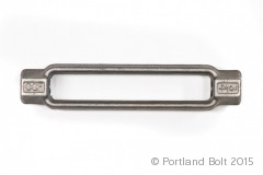
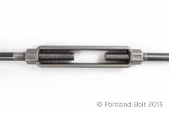
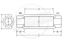
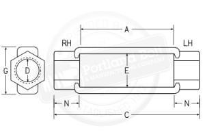
Turnbuckles are a standard component used to extend the length of the assembly or increase the adjustability. They are right hand threaded one end and left hand threaded the other to allow for easy tensioning of the rods. The most common size turnbuckles in a tie rod assembly are 6″ & 12″ takeups; other sizes are available upon request. When ordering galvanized turnbuckles, you will want to confirm that the threads are tapped oversized, especially in the longer lengths.


| Dia. (D), in. | |||||||||||||
|---|---|---|---|---|---|---|---|---|---|---|---|---|---|
| Standard Turnbuckles | Weight in Pounds | Safe Working Load, Kips | |||||||||||
| Dimensions, Inches | Length, Inches | ||||||||||||
| A | N | C | E | G | 6 | 9 | 12 | 18 | 24 | 36 | ASD | LRFD | |
| 1⁄2 | 6 | 25⁄32 | 79⁄16 | 11⁄16 | 15⁄16 | .65 | .90 | 1.20 | 3.67 | 5.50 | |||
| 5⁄8 | 6 | 15⁄16 | 77⁄8 | 13⁄16 | 11⁄2 | .98 | 1.35 | 1.58 | 2.43 | 5.83 | 8.75 | ||
| 3⁄4 | 6 | 11⁄16 | 81⁄8 | 15⁄16 | 123⁄32 | 1.45 | 1.84 | 2.35 | 3.06 | 4.25 | 8.67 | 13.0 | |
| 7⁄8 | 6 | 15⁄16 | 85⁄8 | 13⁄32 | 17⁄8 | 1.85 | 3.02 | 4.20 | 5.43 | 12.0 | 18.0 | ||
| 1 | 6 | 17⁄16 | 87⁄8 | 19⁄32 | 21⁄32 | 2.60 | 4.02 | 4.40 | 6.85 | 10.0 | 15.5 | 23.3 | |
| 11⁄8 | 6 | 19⁄16 | 91⁄8 | 113⁄32 | 29⁄32 | 4.06 | 4.70 | 6.10 | 19.3 | 29.0 | |||
| 11⁄4 | 6 | 19⁄16 | 91⁄8 | 19⁄16 | 217⁄32 | 4.00 | 6.49 | 7.13 | 11.30 | 13.1 | 25.3 | 38.0 | |
| 13⁄8 | 6 | 113⁄16 | 95⁄8 | 111⁄16 | 23⁄4 | 6.15 | 29.0 | 43.5 | |||||
| 11⁄2 | 6 | 17⁄8 | 9-3⁄4 | 127⁄32 | 31⁄32 | 6.15 | 9.70 | 9.13 | 16.80 | 19.4 | 35.0 | 52.5 | |
| 15⁄8 | 6 | 21⁄2 | 11 | 131⁄32 | 39⁄32 | 9.80 | 40.9 | 61.3 | |||||
| 13⁄4 | 6 | 21⁄2 | 11 | 21⁄8 | 39⁄16 | 9.80 | 15.3 | 16.0 | 19.5 | 47.2 | 70.8 | ||
| 17⁄8 | 6 | 213⁄16 | 115⁄8 | 2-3⁄8 | 4 | 14.0 | 15.3 | 62.0 | 93.0 | ||||
| 2 | 6 | 213⁄16 | 115⁄8 | 23⁄8 | 4 | 14.0 | 15.3 | 27.5 | 62.0 | 93.0 | |||
| 21⁄4 | 6 | 35⁄16 | 125⁄8 | 211⁄16 | 45⁄8 | 19.6 | 30.9 | 43.5 | 80.0 | 120 | |||
| 21⁄2 | 6 | 33⁄4 | 131⁄2 | 3 | 5 | 23.3 | 30.9 | 42.4 | 100 | 150 | |||
| 23⁄4 | 6 | 43⁄16 | 143⁄8 | 31⁄4 | 55⁄8 | 31.5 | 54.0 | 125 | 188 | ||||
| 3 | 6 | 45⁄16 | 145⁄8 | 35⁄8 | 61⁄8 | 39.5 | 161 | 242 | |||||
| 31⁄4 | 6 | 57⁄16 | 167⁄8 | 37⁄8 | 63⁄4 | 60.5 | 79.5 | 203 | 305 | ||||
| 31⁄2 | 6 | 57⁄16 | 167⁄8 | 37⁄8 | 63⁄4 | 60.5 | 70.0 | 79.5 | 203 | 305 | |||
| 33⁄4 | 6 | 6 | 18 | 45⁄8 | 81⁄2 | 95.0 | 280 | 420 | |||||
| 4 | 6 | 6 | 18 | 45⁄8 | 81⁄2 | 95.0 | 280 | 420 | |||||
| 41⁄4 | 9 | 63⁄4 | 221⁄2 | 51⁄4 | 93⁄4 | 152 | 390 | 585 | |||||
| 41/2 | 9 | 63/4 | 221/2 | 51/4 | 93/4 | 152 | 390 | 585 | |||||
| 43⁄4 | 9 | 63⁄4 | 221⁄2 | 51⁄4 | 93⁄4 | 152 | 390 | 585 | |||||
| 5 | 9 | 71⁄2 | 24 | 6 | 10 | 200 | 491 | 737 | |||||
|
Dimensions per AISC Manual of Steel Construction thirteenth edition page 15-16 ASD - Allowable Stress Design (according to the AISC 9th Ed.) LRFD - Load and Resistance Factor Design (according to AISC 3rd Ed.) |
|||||||||||||
